|
The order for tool/station use is
pre-determined by shape and size to ensure that parting and secondary operations occur after other tools are used. Overrides for this are easily accessed by the programmer.
Tool Path Control allows programmers to
prescribe how tools are used in a program in terms of both tool order and tool direction. These parameters may be applied as system defaults to tool shapes in general or to individual punches in particular.
Programmers can easily override the system default if specific circumstances call for it.
Default tool path direction (vertical or
horizontal) can be pre-defined for any tool or shape. For shaped tools (rectangles, obrounds, etc.) the punching direction is effected by the key angle of the tool in the station.
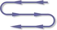
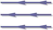
Starting points for each station and the
nature of the punching path, either bi-directional or uni-directional (see illustration on left) may also be pre-determined.
Controls determining the width of a tools
punching path (RANGE) are also available as a system default or as a specific user override (see illustration below). In the case shown, the RANGE might be widened to include the top row of holes.
All of these constraints may be easily overridden by the programmer.
Automatic Bridge Punching is included as an option and is amply illustrated
in the slide show under Intelligent Tool Selection. Nibbling Codes are inserted automatically if the hits in the program meet the machines physical requirements for nibbling
|